The Data Connect RM3UI-R38 & RM14UI-R38
The DCE IG202T-R38 is available in two different types of standard 19” chassis.
The Data Connect DCE/RM3UI-R38 is a 1U chassis with 3 slots for up to quantity three DCE/IG202TRM-R38 Rackmount Modems. The Data Connect DCE/RM3PS-R38 48VDC Power Supply takes up one slot in the DCE/RM3UI-R38 19” Chassis.
The Data Connect DCE/RM14UI-R38 is a 3U chassis with 14 slots for up to quantity fourteen DCE/IG202TRM-R38 Rackmount Modems. The Data Connect DCE/RM14PS-R38 48VDC Power Supply takes up to one slot in the DCE/RM14UI-R38 19” chassis.
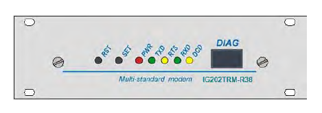
Additional Blank and Rear Plates cover unused slots. All Front LEDs, Reset, Set and Diagnostic Connection are accessible on the front of the DCE/IG202TRM-R38 Rackmount Modems. All rear connectors are accessible at the back openings.
Interfaces
Front Panel
RST Reset button is accessible on the front panel using pin of diameter under 2 mm (pencil tip, etc.). It re-initializes all modem functions. The modem must be reset immediately on inconsistent operation appearance, before starting the maintenance diagnosis phase. This reset, like duration power cut-off, has no effect on the status of configurations previously loaded into the modem.
SET Set button is used for entering command mode (see “Entering Command Mode” section), which allows modem configuration.
PWR In data mode PWR LED is ON when modem is power supplied and in proper function; PWR LED is OFF in case of: power supply is not present or modem is in malfunction. PWR LED blinks slowly (100ms / 1sec cycle) as an indication of command mode. PWR LED blinks fast (100ms / 100ms cycle) when modem has locally initiated some of the test modes. PWR LED blinks slowly (1Sec / 1sec cycle) when modem is remotely brought to some of the test modes.
TXD Transmit LED indicates LED transmitted on TXD pin of RS232 interface.
RTS Request to Send LED indicates state of RTS pin of RS232 interface.
RXD Receive LED indicates data received on RXD pin of RS232 interface.
DCD Data Carrier Detect LED indicates the presence of in-channel carrier with level higher then predefined receive level.
DIAG-Command/Boot-loader serial interface
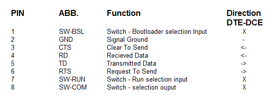
This connector is RJ45 8 pin female type connector. It provides the interface between the modem and terminal unit in command mode and in firmware upgrade process. The following table gives the allocation and function of each pin.
RS-232C / Data serial interface
This connector is a SUB D9 pin female type connector with screw locking. It provides the interface between the modem and remote terminal unit or data processing equipment in data mode. The following table gives the allocation and function of each pin.
Line / Analog interface
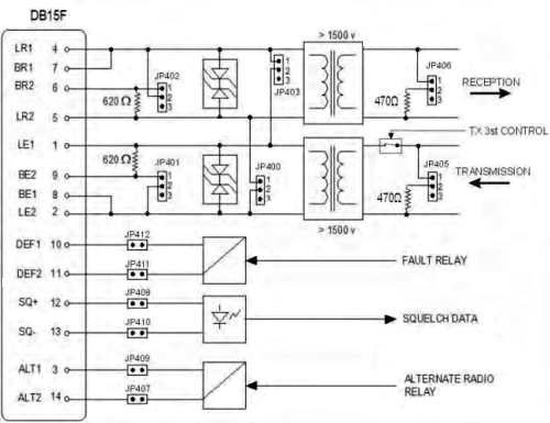
This connecter is a SUB D 15 pin female type connector with screw locking, which provides:
- Interface between 2 or 4 wire analog line and the modem;
- The fail output
On the same connector modem has interface intended for communications management with a radio interface (squelch and alternate) which are not supported in current firmware version. Figure below depicts analog line interface.
Power / Power Supply
Power supply connector is a 2-position screw plug type (for 2-2.5 mm² wire) used for connecting the modem to a DC power supply. Polarity is irrelevant. Maximum consumption is 3VA. Table of possible voltage options are shown below.
IG202T-R38 Rack 1U (up to 3 modems)
IG202T-R38 Rack 3U (up to 14 modems)
Ordering Information
DCE/RM14UI-R38 14 Slot 3UI R38 Chassis 48VDC
DCE/RM3UI-R38 3 Slot 1UI R38 Chassis 48VDC
DCE/RM14PS-R38 48VDC Power Supply for RM14UI-R38
DCE/RM3PS-R38 48VDC Power Supply for RM3UI-R38


